As soon as I got my Technician’s license and my first radio (a Yaesu FT-70DR), I set out to build one of the VHF / UHF (2m / 70cm) tape measure Yagi antennas I had been reading about online. This video got me started with measurements for the tape, etc.
However, there were some details that it left out for first-time antenna builders like me. The most important was how to connect the coax cable to the antenna. I mean, the coax only has one copper wire in it, so how to you connect that one wire to the two rings that connect to the driven elements? I learned from this video that you connect one ring to the wire and one to the wire jacket!
A few other things that I learned the hard way this first build:
- I had read online that RG-8 was preferred for feed lines over other kinds of coax because it’s 50Ω while most coax is 75Ω. That may be true, but the RG-8 was WAY to thick to fit the SMA adapter that connects to my HT. I ended up using some RG-6 (75Ω coax) I picked up at Home Depot instead. Seems to work fine.
- Here’s a time saving tip related to feed line for these homebrew antennas. Since I knew I was intending to build two antennas right off the bat, I was lazy and bought a 25ft finished coax cable at Home Depot. That way I could just cut it into two pieces, and the HT (“handie talkie,” meaning my Yaesu FT-70DR) end of the cable already has a connector on it!
- You will definitely want to screw the tape measure onto the wood frame with the numbers facing UP, so the screws lie in the natural trough of the tape. I attached mine numbers down, which bent and deformed the tape in weird ways. I’m not happy with how floppy the antenna is and in retrospect I know this is part of the reason why.
- One thing I still haven’t figure out: how to drill the holes through the tape measure for the bolts that go through the driven elements. I ended up splitting the tape on all four of these ends and these elements are only held in place by tightening up the nuts quite a lot.
- And yes, you have to line up the UHF driven elements so that they’re exactly above the VHF driven elements. The same two bolts touch all four of them.
Here’s the finished product (lying in the driveway):

I don’t have an SWR meter yet, so I can’t get proper readings on the antenna. However, I’ve used it to grab packet data off the ISS beacon and to listen to conversations on SO-50 (no luck getting my own QSO there yet), so it seems to be working ok.
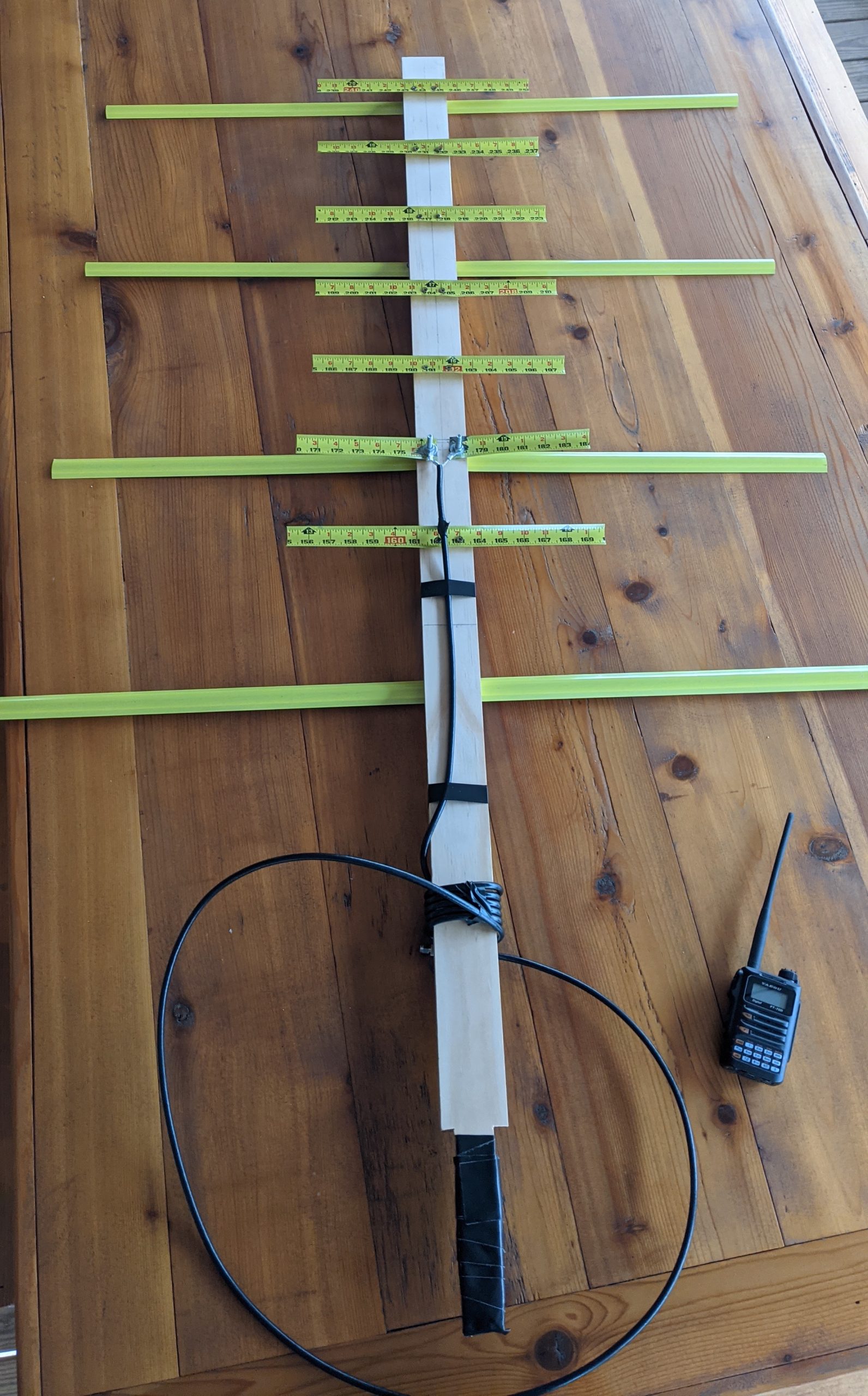
UPDATE: I’ve built another of these antennas incorporating the many lessons I described learning above. One additional piece of advice – use a sturdy tape like the Stanley FatMax. The additional width to the tape makes for far sturdier elements that aren’t so prone to bending in the wind. Here’s the new version (lying on a table with my HT):
